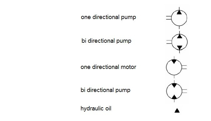
- Pumps and motors
Pumps and hydraulic motors are represented by a circle that input or output power of shaft is drawn by two parallel lines alongside the circle. Triangles inside the circles indicate the flow direction in which the triangle in the pump is outward and in the motor is inward.
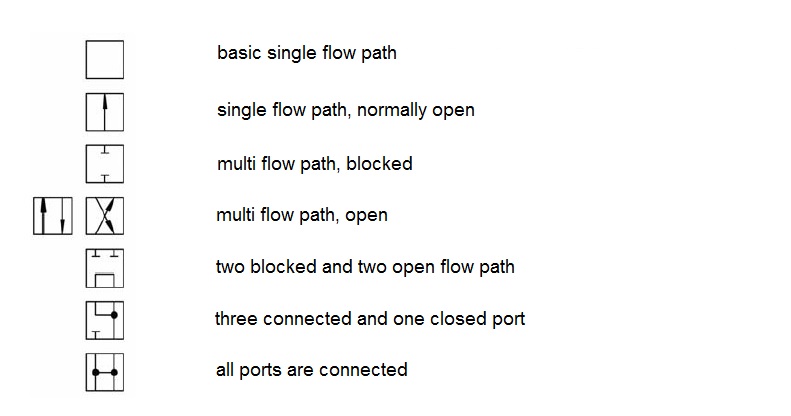
- Directional control valve
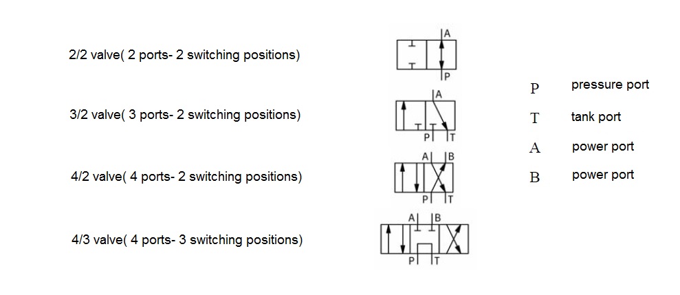
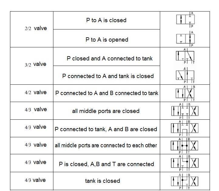
Directional control valves are represented by some connected squares . The number of squares shows the number of switch positions valve . Arrows inside the squares indicate the flow direction. Vertical, horizontal and diagonal lines indicate that how the valve ports in switch positions are connected. For naming directional control valves, first ,the number of ports and then the number of switch positions should be expressed .
Switch positions of directional control valves , is changeable by a variety of actuation methods. Symbol of valve will be completed by mention of it’s method of actuation.
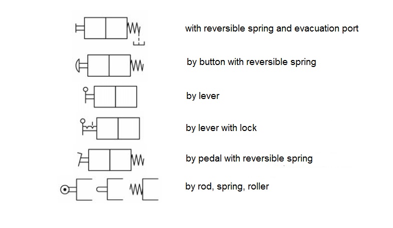
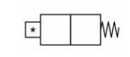
If a standard symbol is not used for actuation , it is necessary to determine the method of actuation by a star and present the necessary information in the description . The shape of lack of using common methods for valve actuation is in the below .
Some examples of directional control valves are presented below:
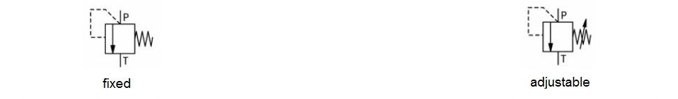
Pressure valves are represented by a square with a arrow that indicates the flow direction . valve ports are specified by Mark P (pressure port), T (tank port) or A or B . The position of the arrows in the squares shows that the normal valve is open or closed.
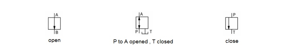
Another difference between pressure valves is to be adjustable or constant that the first case is specified by a diagonal line .
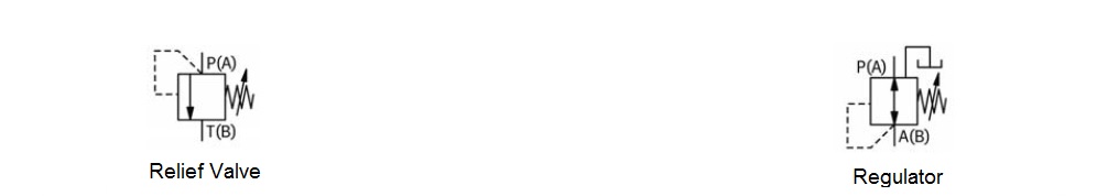
Pressure control valves are divided to two groups : Relief valves and regulator valves. Relief valves are closed in normal situation and pilot pressure is taken from input. However, the regulator valves are open in normal situation and the pilot pressure is taken from outside.
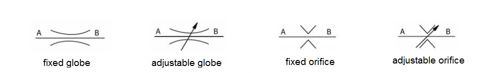
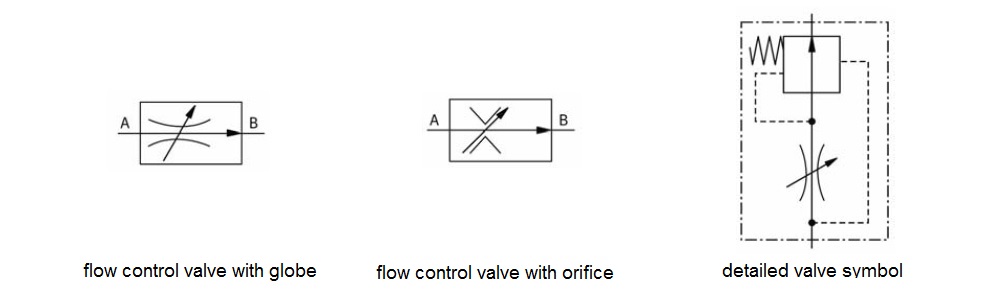
In terms of flow control valves, there is a main difference between the valves .the Valves which are not affected by viscosity changes ,are named Orifice and the valves which viscosity changes effect on their performance are named Globe .
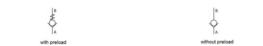
- One-way Valve
The symbol of one-way valves is as a ball on the seat of sealing flow . The location of the ball is a wide angle .the Tip of wide angle shows the direction of the closed flow.
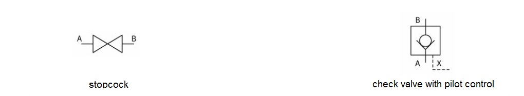
The symbol of check valves with pilot performance is represented as a check valve in a square . control pilot of the valve is drawn with dashed line under the square. switching valves are represented by two triangles facing each other. These valves are usually used to drain the oil reservoir or drain the accumulator pressure.
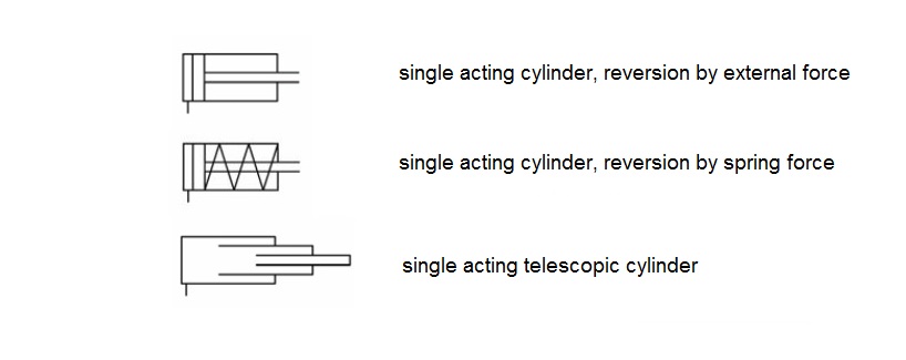
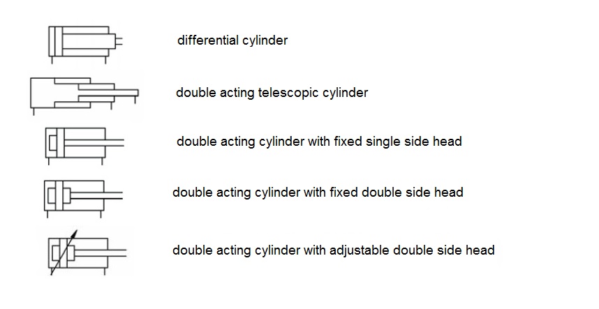
Cylinders are classified in two categories of single-acting and double-acting. Single-acting cylinders have only one port ,it means that only the area of their whole diameter is under hydraulic pressure . These cylinders are opened under the influence of external forces such as the weight or spring force.
Double-acting cylinders have two ports for the entry and exit of oil that in this way oil will be transferred to the front and rear piston and cylinder will move .one-way Dual-acting cylinders, piston rod is on one side only, while the double-acting cylinder have two piston rods on two sides of it.
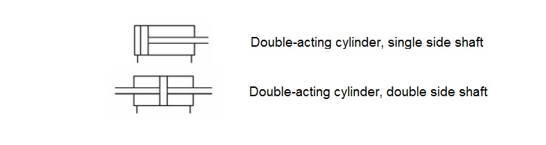
The differential cylinder, the area of the piston, is double of the piston ring . the symbol of this cylinder will be specified from other cylinders by adding two parallel lines at the front of piston rod.
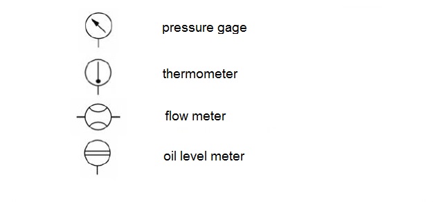
- Sensors and Instrumentations
The equipment for measuring temperature, pressure, flow rate and etc. in hydraulic circuit will be specified by their own specific symbol.
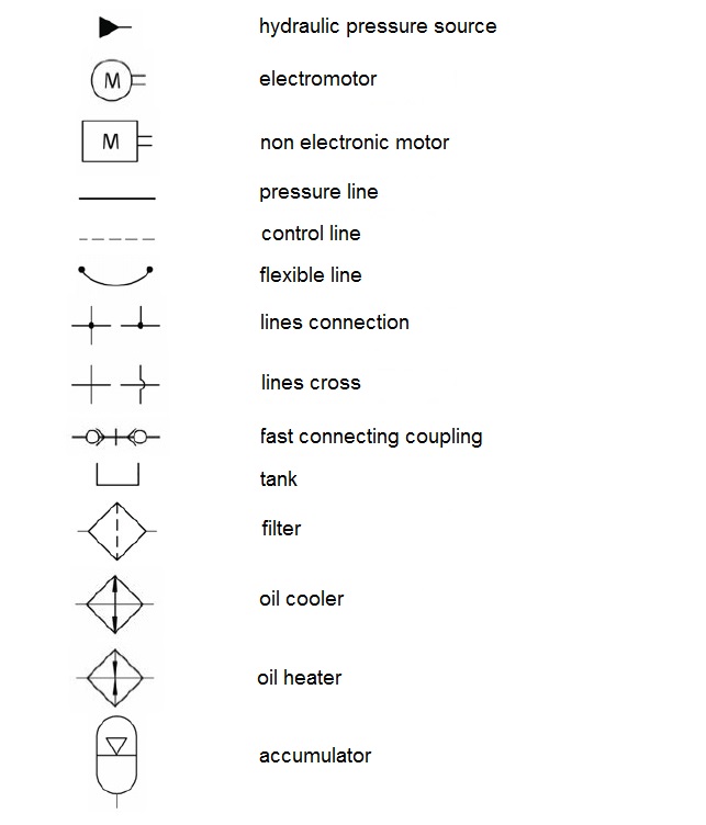
- Energy transfer and oil preparation
The following symbols are used to show energy transfer and oil preparation equipment used in the hydraulic circuit: